Voron v2.4 AWD Mod
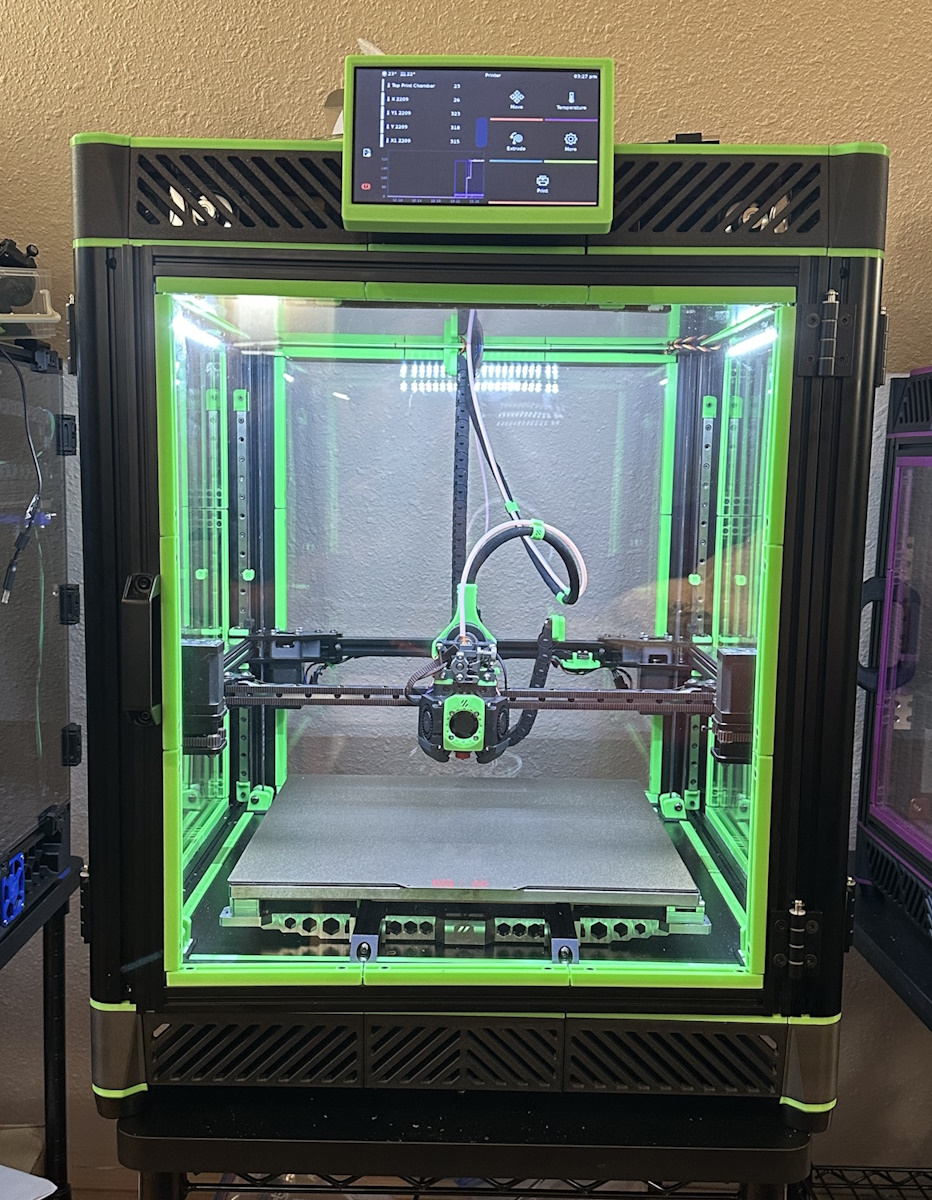 Image Credit: @k3v00o00 on the Voron Discord
Getting Started
So you're thinking about burning some money?
Visualization of space lost with NEMA14s with Xol toolhead on a 350mm bed.
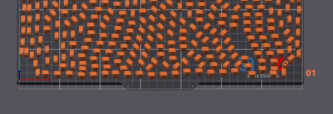 Image Credit: @.skeebo on Armchair Heavy Industries Discord
But Why?
- Pros
- You will be able to (probably) print faster with less vibration.
- Having two steppers per belt helps equalize the tension on the belt during fast moves.
- Metal (if you use them) plates help dissipate heat from your steppers, so you can run higher currents.
- Looks cool. Bling is always a good thing.
- Works with existing XYjoints.
- You will be able to (probably) print faster with less vibration.
- Cons
- If modifying an existing printer (or building from BOM or a Kit) you will lose a small amount of bed space.
- For NEMA14s, you will lose between 10x10mm and 20x20mm of space, depending on the toolhead you use.
- For the original NEMA14 plates (and Funssor CNC plates) this is more like 20x20 to 30x30.
- For NEMA17s, you can expect to lose betweeen 25x25 and 40x40mm of space.
- For NEMA14s, you will lose between 10x10mm and 20x20mm of space, depending on the toolhead you use.
- Need to replace your XY belts
- Cost and complexity
- If modifying an existing printer (or building from BOM or a Kit) you will lose a small amount of bed space.
Sourcing / BOM
Affiliate Link Disclosure
Some of these links contain affiliate codes. If you buy through an affiliate link, I may earn a commission on your purchase.
Stepper Size Choice
The first big choice you need to make is which size steppers you are going to use. NEMA14s take up significantly less space and are plenty powerful. If you don't mind losing some printable area then NEMA17s are a good choice too.
Recommended Steppers:
NEMA14
- LDO LDO-35STH52-1504AH(VRN)
- Moons MS14HS5P4200
NEMA17
Vendors
These vendors have pre-cut plates in stock and ready to ship.
- UK
- EU
- US
- China
Self-Sourcing
Tip
Recommended material: 5052 Aluminium, 0.125"/~3.2mm
- US
- Europe
- LaserBoost (Spain)
- Use 3mm 5754 Aluminium for all parts
- LaserTeileOnline (Germany)
- Use 3mm ALMG3 Aluminium for all parts
- LaserBoost (Spain)
- China
BOM
Please Note
The original NEMA14 plates (and Funssor CNC plates) will require 4 extra F695-2RS Bearings.
NEMA14
- 16x F695-2RS Bearings
- 8x F623-2RS Bearings
- 2x M5x30mm
- 2x M5 Nuts
- 6x 20mm M3 Metal Standoffs (or DoubleT pins)
- 12x M3x8mm
- 16x M3x30mm
- GT2-6 Belt
NEMA17
- 16x F695-2RS Bearings
- 12x F623-2RS Bearings
- 2x M5x30mm
- 2x M5 Nuts
- 6x 20mm M3 Metal Standoffs (or machined pins)
- 12x M3x8mm
- 16x M3x30mm
- GT2-6 Belt
Standoffs or Pins
Warning
While you can get away with M3x20mm standoffs, they are a bit of a crapshoot for fitment. You may have to sand a bit.
Sources:
- Machined (DoubleT) Pins:
- M3x20mm Pins:
Printed Parts
- The printed parts are listed in the STL directory of the GitHub repo under either STL/NEMA14/MetalPlates or STL/NEMA17/MetalPlates depending on your stepper size.
- If your Rear Plates aren't all identical (ie, v1 plates), you'll need to print the 'v1 Plate' parts in the MetalPlates folder instead of the 'Rear_Clamp_Grip" and "Rear_Clamp".
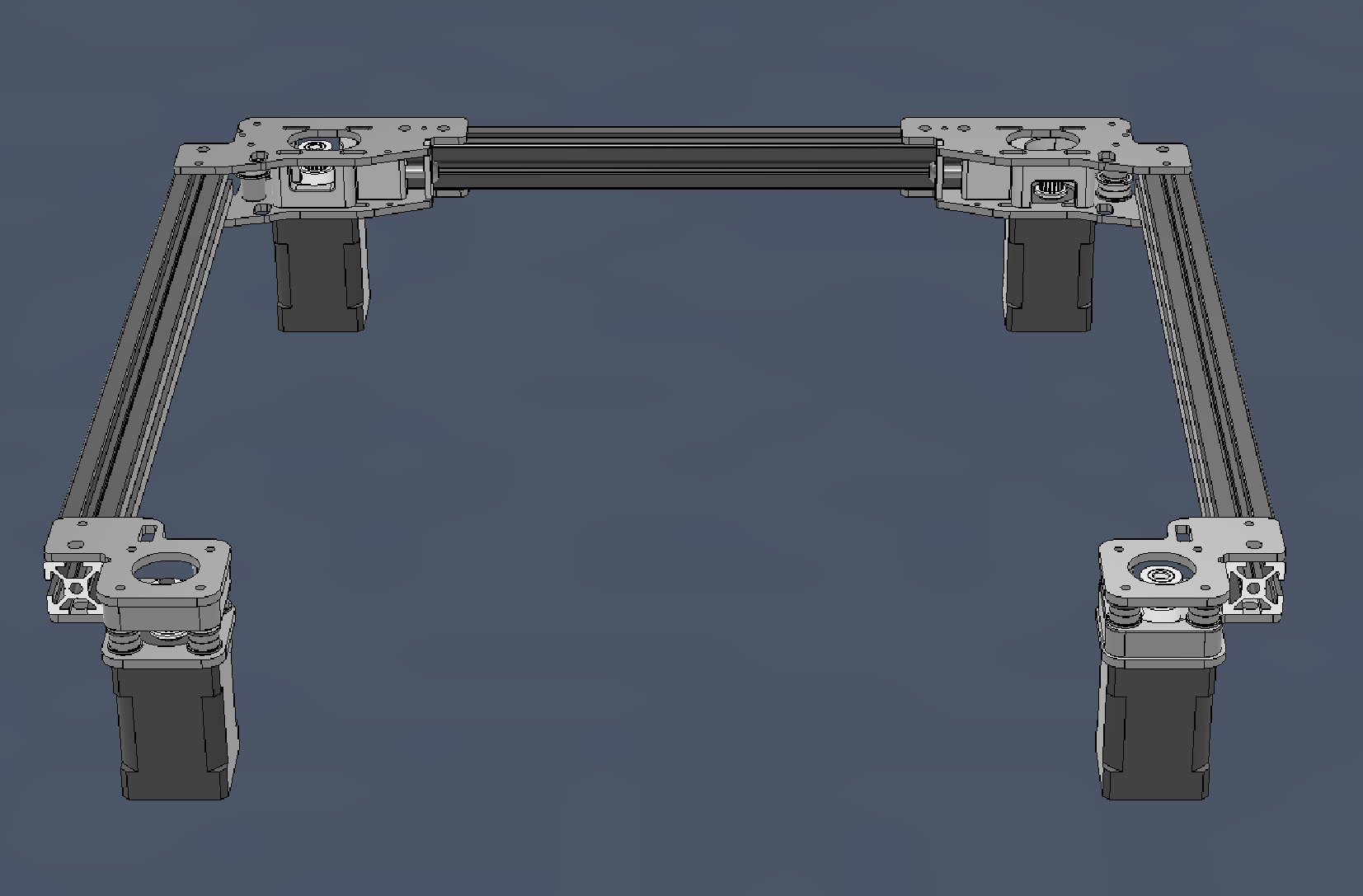
Assembly
Use the CAD for info on how to assemble.
Filing for Fitment
Laser cut parts aren't perfect, it's likely that you will have to sand or file some parts to knock off burrs or to ensure a tight fit. If your parts are anodized, consider which area will be most visible before filing.
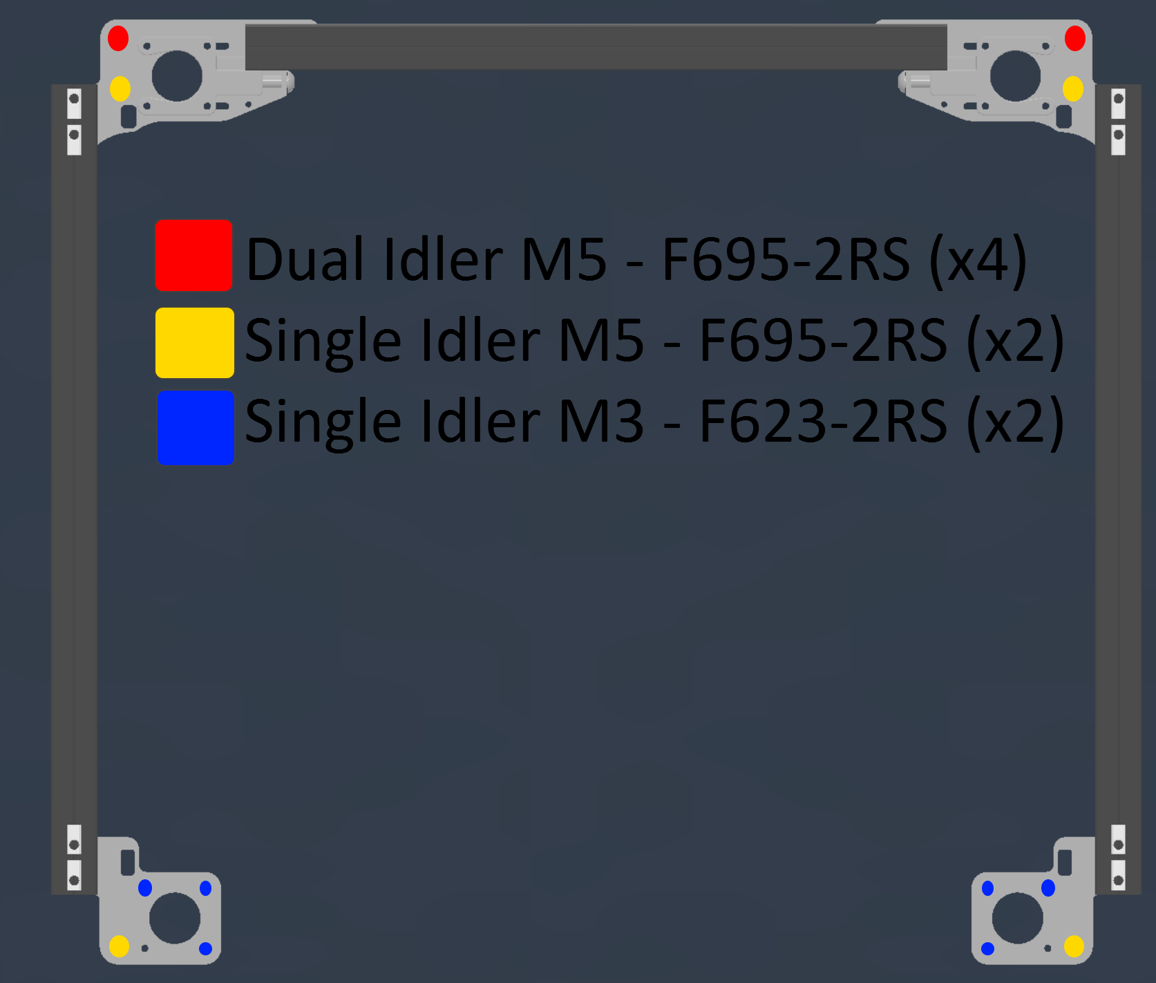
NEMA14 Bearing Idler Stacks
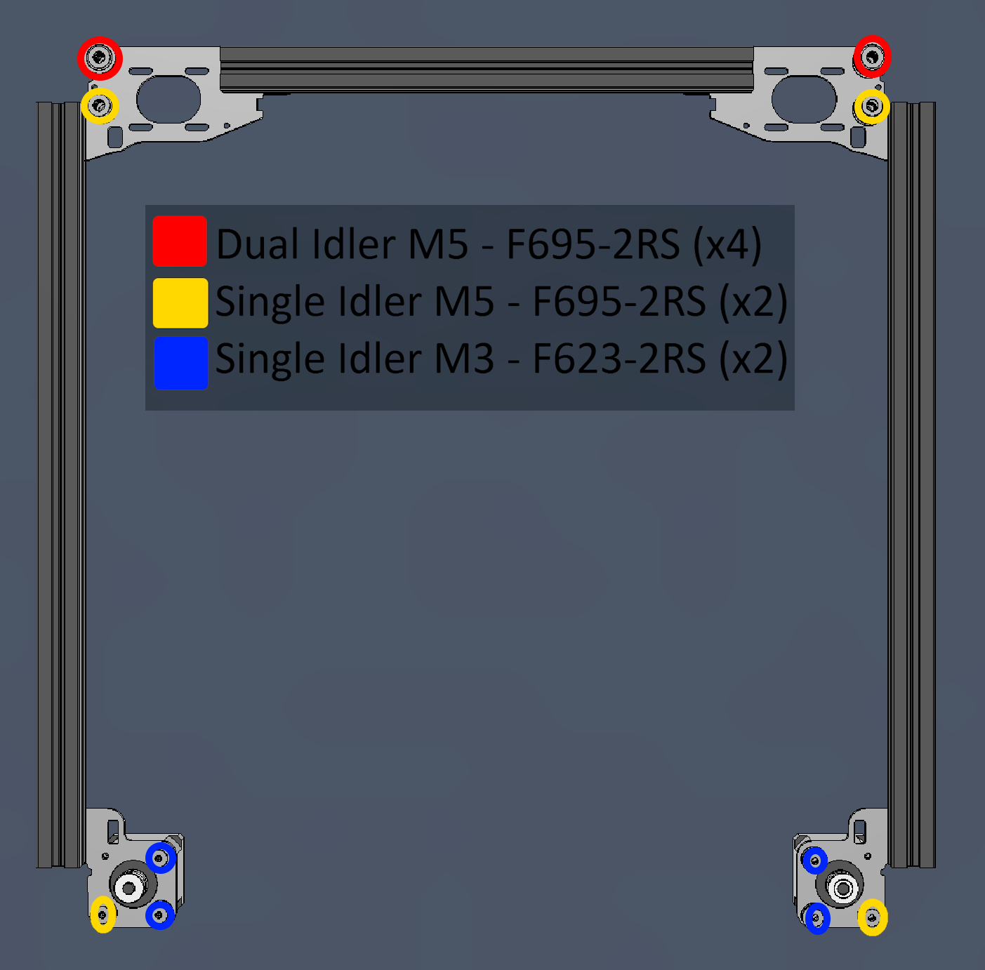
NEMA17 Bearing Idler Stacks
Please Note
These are also the idler locations for the original NEMA14 (and Funssor CNC plates) plates.
Belt Pathing
The belt pathing for AWD is swapped compared to a stock v2.4. This is to keep compatibility with stock and aftermarket XY-joints.
- Your A Stepper (Back-Right) will be on the lower belt and the B Stepper (Back-Left) will be on the upper belt.
- This means the Front-Left Stepper will be on the lower belt and the Front-Right Stepper will be on the upper belt.
Tensioning
- Loosen the 4 stepper mounting bolts slightly so the whole tensioner can move freely and move it to the slackest setting.
- If you do not loosen them enough, you WILL bow the tensioner plate.
- Ensure the belts are well secured and tensioned equally at the toolhead.
- Your belts should be equal in length and have the same amount of teeth sticking out past the toolhead.
- Turn the M5 bolt clockwise to increase tension to desired amount.
- Tighten the 4 stepper mounting bolts before testing.
Klipper Configuration
Changes needed
-
Config in Klipper is straight-forward as you're just adding an additional stepper for X and Y. I named them
Stepper_X1andStepper_Y1. Very creative, I know. -
Be sure to test your config by doing a
STEPPER_BUZZ STEPPER={namegoeshere}to verify they are moving the correct way. More info in the Klipper Docs. -
Carefully test to determine how much of an exclusion zone you'll need to set in your slicer for each of the front corners if using AWD.
Config Reference
- The configuration for the test printer with AWD can be found in my backup repo here: config/steppers_xy.cfg
Slicer Configuration
- PrusaSlicer and SuperSlicer can be configured with custom bed shapes to allow for the bed exclusion zones at the front corners.
- These custom bed shapes are defined with an STL. There is an OpenSCAD script to generate a custom STL here.
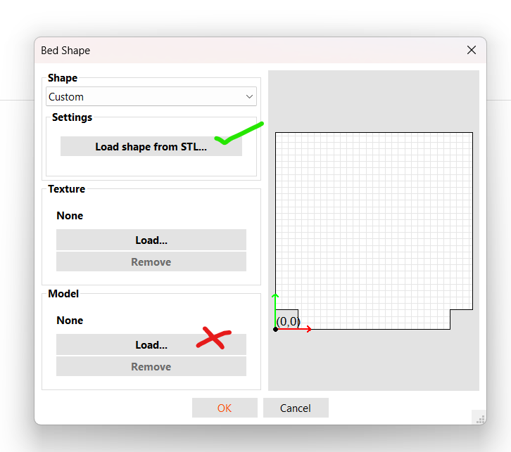
- Set the Bed Shape to 'Custom' and load the shape via STL. Do not load it as a 'Model'.
-
If you've previously loaded a 'Model', you will need to remove it. Make sure it says 'None' in the 'Model' area. See the below image.
Still Have Questions?
You can find discussion about this mod in:
- Armchair Heavy Industries Discord - There is a thread in
user-projects - There is a thread in VOC_Works on the Voron Discord - you need a serial to access that area.